Remote-controlled robotic arm
Project
This project is a collaborative project for my bachelor's graduation project and completed by a team of three. It is titled "Development of an Inertial-Sensing-Based Intelligent Human-Machine Collaborative Robotic Control System."
The objective of this project is to develop an inertial-sensing-based intelligent human-machine collaborative robotic control system.
The functions of this system include:
1. real-time human motion tracking and remote control;
2. human-machine collaborative monitoring interface.
We have executed the following four research subjects to accomplish the aforementioned objectives:
1. Develop a wearable sensing device placed on human arm to implement a real-time, convenient, and low-cost wearable body sensor network.
2. Develop a robotic arm control system with high degrees of freedom (DOF) through the robotic arm model analysis.
3. Develop a real-time human motion tracking and control algorithm to integrate the wearable body sensor network and the robotic arm control system for implementing a real-time, convenient, and low-cost intelligent human-machine collaborative robotic control system.
4. Develop a human-machine collaborative monitoring interface to display human motion signals and the results of the human motion tracking. Finally, the experimental results have successfully validated the effectiveness of the proposed intelligent human-machine collaborative robotic control system and its human-machine collaborative monitoring interface.
My role is for intergrating the wearable device, designing and constructing the project’s robotic arm system, I developed the algorithm for the arm’s movement and conducted the Denavit-Hartenberg representation analysis. Based on this analysis, I customized a humanoid robotic arm, assembling it with five motors and utilizing 3D software and a 3D printer to construct the connections between them. After creating the robotic arm, I derived its forward kinematics. I used MATLAB to program the motion algorithm and forward kinematics, integrating these with the human-machine interface my team designed in LabVIEW. This enabled seamless operation and monitoring of the robotic arm
Project Components
This project involves constructing an intelligent human-machine collaborative robotic arm that mimics the human arm. Each part of the human arm is treated as an independent rigid body. Considering the characteristics and corresponding movement constraints of each joint, the connections between the rigid bodies can be classified into shoulder joints and elbow joints. The shoulder joint has three degrees of freedom, the elbow joint has one degree of freedom, and the forearm has one degree of freedom.
As a result, three servo motors are installed at the shoulder joint, one at the elbow joint, and one at the forearm, corresponding to the degrees of freedom of these parts. This ensures that the movements reconstructed by the intelligent human-machine collaborative robotic arm are closer to the real movements of a human arm.
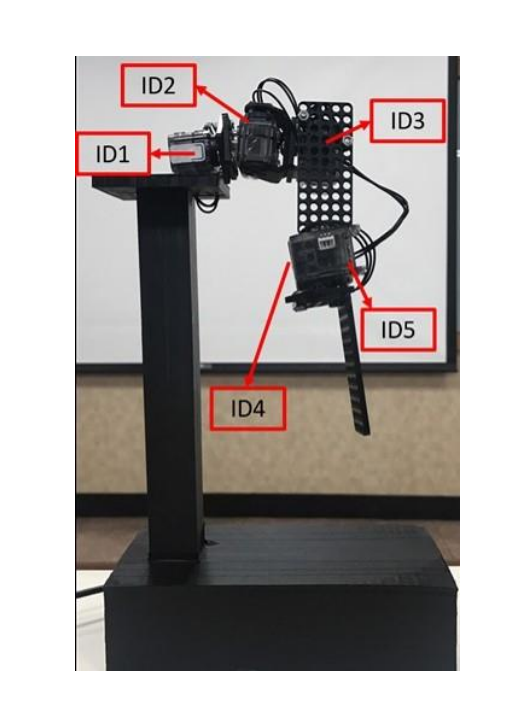
A schematic diagram of the physical model of the robotic arm
The wearable human motion sensing device developed in this project has dimensions of 56.0 mm × 37.0 mm × 15.0 mm. By utilizing this wearable sensing device, inertial sensing signals are measured and processed through signal preprocessing and Kalman filter calculations. This allows for obtaining the roll, pitch, and yaw angles during motion. The processed data is then transmitted to the computer receiver via an RF wireless transmission module for coordinate transformation, ultimately obtaining the final posture to control the intelligent human-machine collaborative robotic arm.
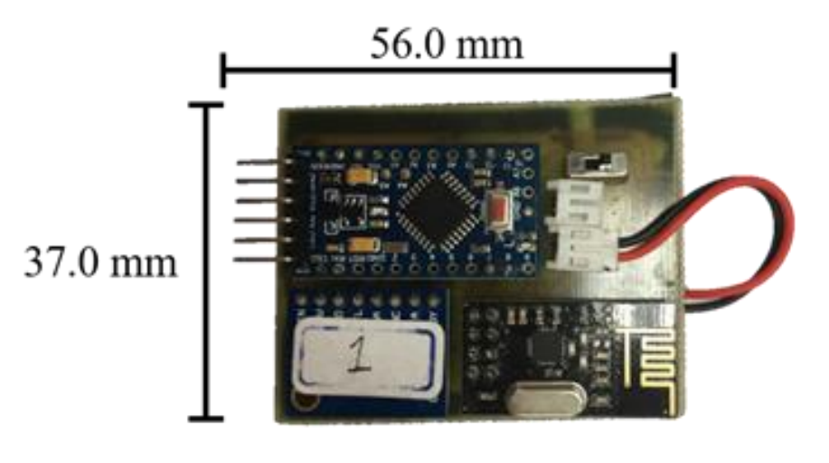
Wearable electronic device
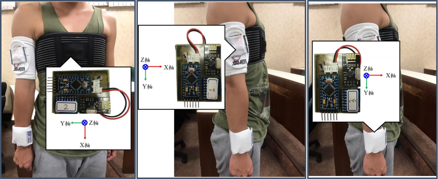
The placement diagram of the wearable human motion sensing device on the human arm
Denavit-Hartenberg Matrix (D-H Matrix)
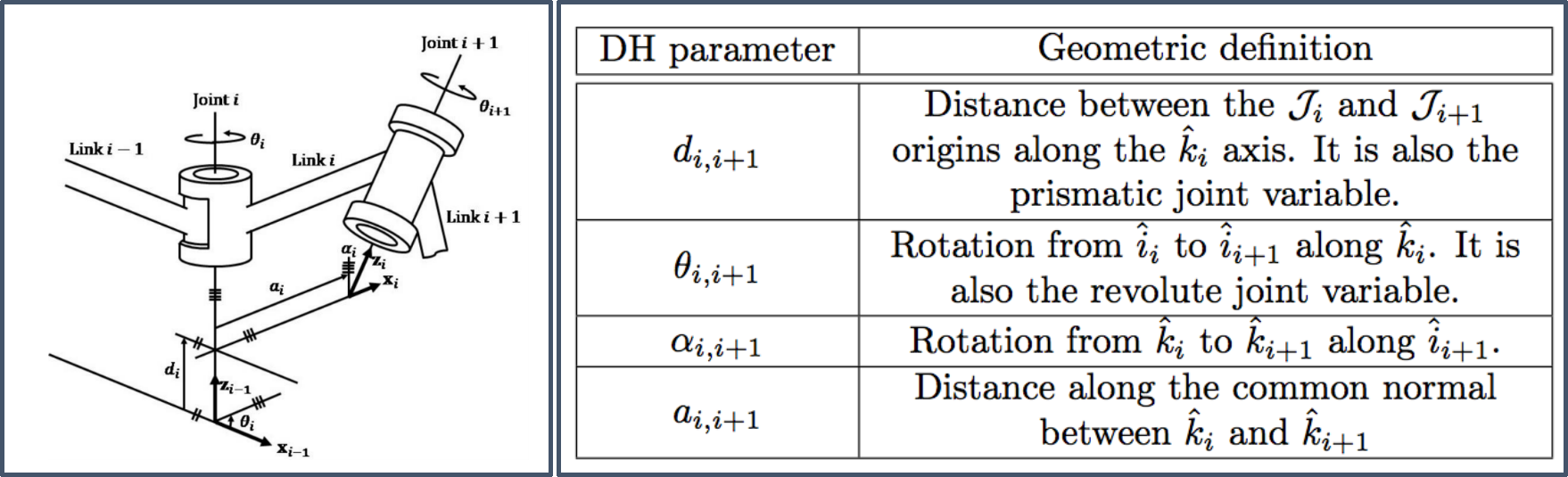
Link coordinate diagram of the robot arm
Based on the joints’ relationship table and diagram above, we can construct a D-H parameter table for this customized robot arm:
-
When the shoulder joint rotates around the internal-external axis of the body in the sagittal plane, the motor coordinate system is defined as the zero coordinate system, and the rotation angle is denoted as 𝜃₁.
-
When the shoulder joint rotates around the vertical axis of the body in the transverse plane, the motor coordinate system is defined as the first coordinate system, and the motor’s rotation angle is denoted as 𝜃₂.
-
When the shoulder joint rotates around the anterior-posterior axis of the body in the coronal plane, the motor coordinate system is defined as the second coordinate system, and the rotation angle is denoted as 𝜃₃.
-
When the elbow joint rotates around the anterior-posterior axis of the body in the coronal plane, the motor coordinate system is defined as the third coordinate system, and the rotation angle is denoted as 𝜃₄.
-
When the forearm rotates around the vertical axis of the body in the transverse plane, the motor coordinate system is defined as the fourth coordinate system, and the rotation angle is denoted as 𝜃₅.
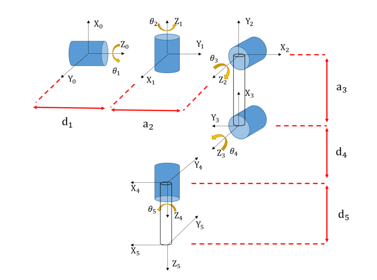
The schematic of motor orientation is designated using the Denavit-Hartenberg (DH) algorithm
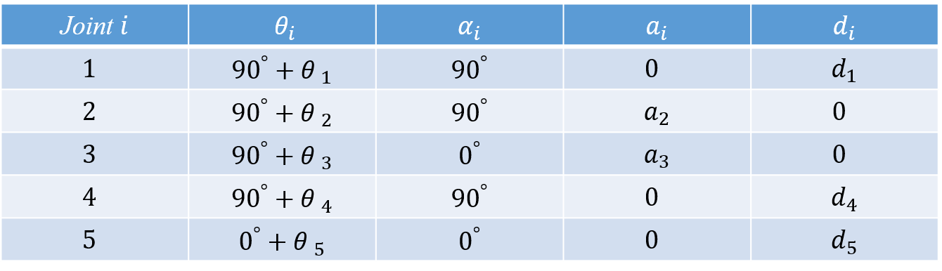
Joints table
Kinematic Algorithm
Based on the definitions of each motor’s coordinate system and rotation angles:
- The angle of the shoulder joint’s rotation around the internal-external axis.
- The angle of the shoulder joint’s rotation around the vertical axis.
- The angle of the shoulder joint’s rotation around the anterior-posterior axis.
We can design the zero coordinate system, first coordinate system, and second coordinate system as part of the shoulder joint in the intelligent human-machine collaborative robotic arm system. To more accurately calculate the position of the arm’s endpoint, we must also account for the distances between these three coordinate systems, represented by d₁ and a₂.
According to the D-H coordinate system link parameters:
- The Zᵢ₋₁ axis coincides with the Joint i axis.
- The zero coordinate system rotates counterclockwise by 90° around the X₁ axis to align with the first coordinate system, so 𝛼₁ = 90°.
- The zero coordinate system shifts along the Z₀ axis to move its origin to the intersection of X₁ and Z₀, with a distance of d₁. According to the D-H coordinate system rules, a₁ is the distance measured along the X₁ axis between Zᵢ₋₁ and Zᵢ, so a₁ = 0.
Next, the first coordinate system rotates counterclockwise by 90° around the X₂ axis to align with the second coordinate system, so 𝛼₂ = 90°.
- The first coordinate system shifts along the X₂ axis from Z₁ to Z₂ by a distance of a₂. According to the D-H coordinate system rules, d₂ is the distance measured along the Z₁ axis from its origin to the intersection of the X₂ axis and the Z₁ axis, so d₂ = 0.
The distance from the second coordinate system to the third coordinate system represents the length of the arm from the shoulder to the elbow. This is set as a₃. According to the D-H parameter rules, d₃ is the distance measured along the Z₂ axis to the intersection of the X₃ axis and the Z₂ axis, so d₃ = 0. Since the Z₂ axis coincides with the Joint 3 axis, no rotation is needed, so 𝛼₃ = 0.
The third coordinate system is designed as the elbow joint of the intelligent human-machine collaborative robotic arm system. The fourth coordinate system represents the forearm in the system. Although the positions of the two coordinate systems overlap, the distance between them is still considered, so there is a value for d₄.
- The third coordinate system shifts along the Z₃ axis to the fourth coordinate system, with a distance of d₄. According to the D-H coordinate system rules, 𝛼₄ = 90° because the third coordinate system rotates counterclockwise by 90° around the Z₄ axis to align with the fourth coordinate system.
The fourth coordinate system represents the forearm, and the fifth coordinate system represents the endpoint of the robotic arm. The distance between these two coordinate systems is denoted as a₄. According to the D-H coordinate system rules, d₅ = 0 because the fourth coordinate system is aligned with the fifth coordinate system.
Finally, by multiplying the rotation matrices of each coordinate system in sequence, we can obtain the forward kinematics analysis of the intelligent human-machine collaborative robotic arm system.
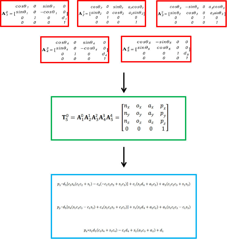
The final calculation of the Kinematic algorithm
Project Results
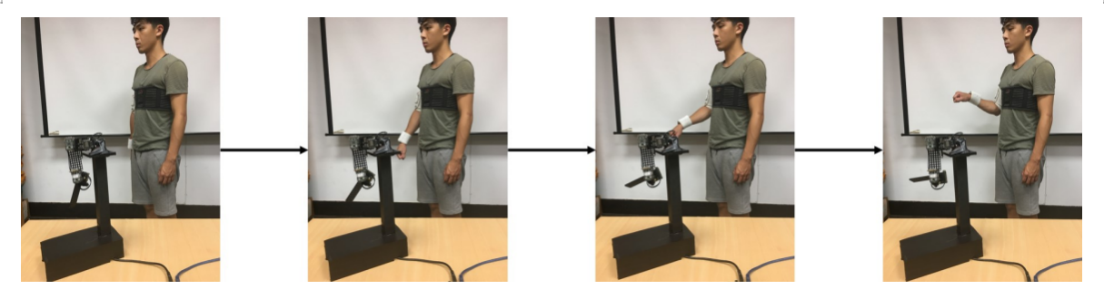
- Shoulder Joint Horizontal Abduction
First, by moving the upper arm horizontally to the right, the shoulder joint abduction motion is demonstrated. The motor with ID 2 on the intelligent human-machine collaborative robot arm corresponds to the yaw angle of the human shoulder joint. We control the rotation angle of the motor with ID 2 using the yaw angle from the upper arm wearable human motion sensing device.
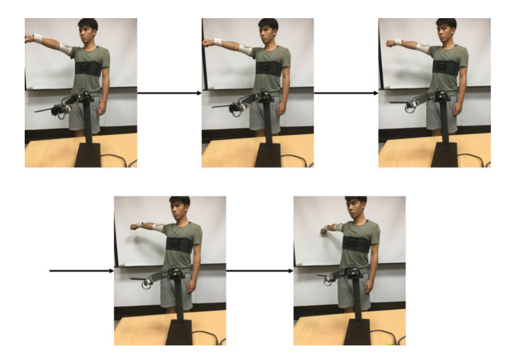
Shoulder Joint Horizontal Abduction
- Shoulder Joint upper arm extension
In the case of shoulder joint arm rotation, the human arm exhibits internal and external rotation. The motor with ID 1 on the intelligent human-machine collaborative robot arm corresponds to the pitch angle of the human shoulder joint. We control the rotation angle of the motor with ID 1 by using the pitch angle from the upper arm wearable human motion sensing device.
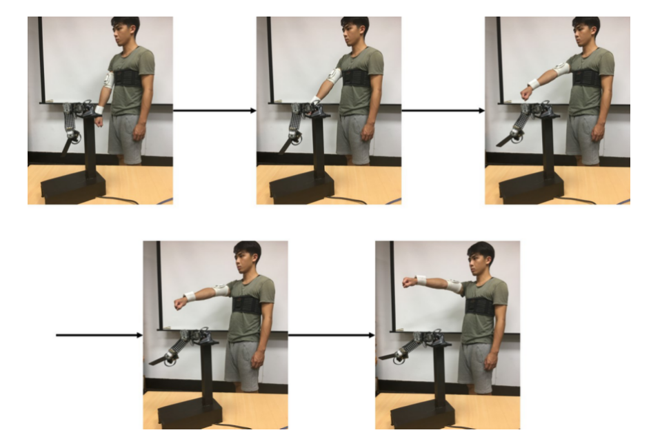
Shoulder joint upper arm extension
- Shoulder Joint upper arm rotation
In the case of shoulder joint arm extension, the arm is raised upwards in a lifting posture. The motor with ID 3 on the intelligent human-machine collaborative robot arm corresponds to the rolling angle of the human shoulder joint. We control the rotation angle of the motor with ID 3 by using the rolling angle from the upper arm wearable human motion sensing device.
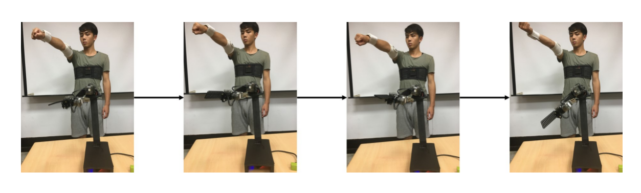
Shoulder joint upper arm rotation
- Elbow joint flexion and extension
In the case of elbow joint flexion and extension, the forearm is bent upwards in a hanging posture. The motor with ID 5 on the intelligent human-machine collaborative robot arm corresponds to the rolling angle of the human elbow joint. We control the rotation angle of the motor with ID 5 by subtracting the rolling angle of the upper arm wearable human motion sensing device from the rolling angle of the forearm wearable human motion sensing device.